
vip@mingyuforklift.com
+86-0535-2090977

The seemingly simple question of an unloaded electric forklift's center of gravity (CG) belies a complex interplay of design considerations, component placement, and operational safety. Understanding the location of this crucial point is paramount for ensuring stability, preventing tip-overs, and optimizing the performance of these ubiquitous material handling machines. This article delves into the factors influencing the CG of an unloaded electric forklift, explores its typical location, and discusses the implications for safe and efficient operation.
Fundamental Principles: The Center of Gravity Explained
Before pinpointing the CG of electric forklifts, it's essential to grasp the fundamental concept. The center of gravity, also known as the center of mass, is the theoretical point where the entire weight of an object is considered to be concentrated. For a uniformly dense object with a symmetrical shape, the CG lies at its geometric center. However, forklifts are far from uniform or symmetrical, comprising numerous components with varying weights and distributions.
The CG is critical for stability because an object will remain stable as long as its CG lies within its support base. In the case of a forklift, the support base is defined by the contact points of its wheels with the ground, forming a stability triangle (for three-wheeled forklifts) or a stability rectangle (for four-wheeled forklifts). When the CG shifts outside this stability area, the forklift becomes unstable and risks tipping over.
Factors Influencing the Unloaded Electric Forklift's Center of Gravity
Several key design and component placement decisions significantly impact the location of an unloaded electric forklift's CG:
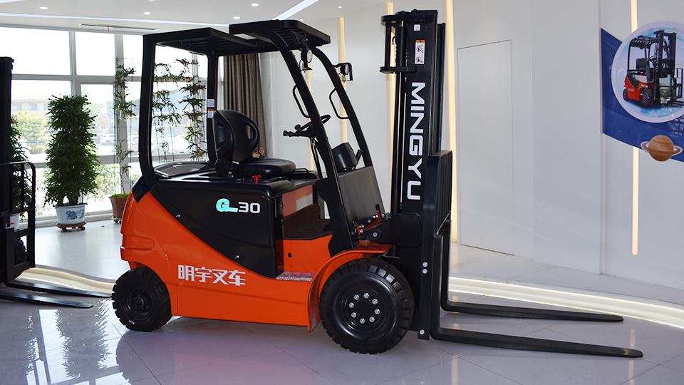
Battery Placement: In electric forklifts, the battery is typically the single heaviest component. Its placement is a primary determinant of the overall CG. To enhance stability, especially when lifting loads, manufacturers often position the battery low and towards the rear of the forklift. This counterbalances the weight of the mast and any potential load. Different battery mounting configurations exist, including side extraction, top extraction, and rear placement, each influencing the CG slightly. A lower battery position contributes significantly to a lower overall CG, improving resistance to longitudinal tipping. Rear placement helps shift the CG rearward, counteracting the forward weight bias of the mast.
Mast Assembly: The mast, with its steel structure, lift cylinders, and carriage, constitutes a significant portion of the forklift's weight. Its vertical orientation and forward placement naturally shift the CG forward compared to a simple chassis without a lifting mechanism. The specific design of the mast (single-stage, two-stage, three-stage), its extended height, the materials used in its construction (e.g., standard steel vs. high-strength alloys), and the weight of the carriage itself all contribute to its overall weight and its influence on the longitudinal CG. Heavier and more extended masts will exert a greater forward pull on the CG.
Chassis and Frame Design: The structural frame of the electric forklift truck provides the foundation for mounting all other components. Its material (typically steel with varying thicknesses), overall shape, and internal bracing contribute to the base CG of the machine before other elements are added. Manufacturers strive for a robust yet balanced chassis design, often incorporating heavier sections in the rear to further aid in counterbalancing. The distribution of weight within the chassis itself, considering factors like the thickness of steel members and the placement of reinforcing plates, plays a subtle but important role in the initial CG.
Drive and Steering Axles: The weight and placement of the drive motor(s), transmission (if applicable – many electric forklifts use direct drive), differential, and steering mechanism also influence the CG. Electric forklifts often have the drive motor(s) located near the drive axle(s), contributing to the weight distribution in that area. The design of the axles themselves, including the materials and the size of the gears and housings, adds to the overall weight distribution. The steering axle, typically located at the rear, also contributes to the overall weight and influences the longitudinal CG.
Operator Compartment and Controls: The operator's seat (especially if it has suspension mechanisms), overhead guard (if fitted – a substantial safety feature adding weight up high), control levers, dashboard, and any integrated electronics (controllers, displays) add weight to the forklift. While individually these components may not be as heavy as the battery or mast, their positioning within the overall structure contributes to the final CG. The height of the overhead guard, in particular, can slightly raise the overall CG.
Tires and Wheels: The type and size of tires (solid rubber, pneumatic, polyurethane), the material and weight of the rims, and the presence of any wheel weights contribute to the overall weight distribution at the base of the forklift. While their direct impact on the vertical CG might be minimal compared to heavier components, they define the stability base and influence the distribution of the forklift's weight across the ground. Larger and heavier tires and wheels will contribute more to the overall weight.
Hydraulic System: The hydraulic pump, reservoir (containing hydraulic fluid), hoses, cylinders (lift and tilt), and control valves, while essential for lifting and tilting functions, add weight to the system. Their placement, typically within the chassis and near the mast, contributes to the overall weight distribution. The volume of hydraulic fluid in the reservoir and cylinders will also have a minor impact on the overall weight and CG.
Typical Location of the Unloaded Electric Forklift's Center of Gravity
Considering the interplay of these factors, electric forklift batteries, the unloaded electric forklift's center of gravity is generally located:
Vertically: Relatively low to the ground. This is primarily due to the heavy battery being positioned at the base of the forklift. A lower CG significantly enhances lateral and longitudinal stability, reducing the tendency to tip over during travel, turning, and maneuvering without a load. The proximity of the battery mass to the ground provides a strong stabilizing effect.
Longitudinally (Front to Back): Slightly forward of the midpoint between the front and rear axles, and typically located within the rear half of the forklift's overall length. This forward bias is primarily due to the weight of the mast assembly extending in front of the chassis and the counterbalancing effect of the rear-mounted battery. The exact position along the longitudinal axis is a critical design parameter, balancing maneuverability with inherent stability. Manufacturers carefully calculate this to ensure a stable platform without compromising the forklift's ability to navigate tight spaces. However, it's crucial to understand that this is a general trend, and the exact location will vary depending on the specific model, its wheelbase, and the weight distribution of its components. Some manufacturers might design for a CG closer to the midpoint for better weight distribution in certain applications or for specific performance characteristics.
Laterally (Side to Side): Very close to the longitudinal centerline of the forklift. Electric forklifts are meticulously designed to be laterally symmetrical to ensure balanced stability during turns and when operating on slightly uneven surfaces. Any significant lateral shift in the CG would drastically compromise stability and substantially increase the risk of side tip-overs, which can be particularly dangerous. The symmetrical placement of major components, including the battery (often centrally located), drive motors, and chassis structure, contributes to this lateral balance.
Importance of Knowing the Unloaded CG Location
While the unloaded CG is different from the loaded CG (which shifts significantly forward and potentially upward when a load is engaged), understanding its location is crucial for several fundamental reasons:
Baseline Stability Assessment: The unloaded CG establishes the inherent stability characteristics of the forklift when it is not carrying any load. It dictates the forklift's natural resistance to tipping during activities like traveling on level ground, negotiating slight inclines, and making turns without a load. This baseline stability is a crucial factor in the overall safety profile of the machine.
Load Capacity and Stability Calculations: Manufacturers rely on the unloaded CG as a primary reference point when determining the forklift's rated load capacity at various load centers (the horizontal distance from the front face of the forks to the load's center of gravity). The predictable shift in the overall CG when a load is added is a critical variable in these complex stability calculations. Knowing the unloaded CG allows engineers to accurately predict how the addition of a load will affect the forklift's stability limits.
Operator Training and Safe Operating Procedures: Operators must have a fundamental understanding of the concept of CG and how it influences stability, even when the forklift is unloaded. This knowledge is essential for safe maneuvering, especially when operating on ramps or uneven terrain, where even the unloaded CG can shift outside the stability triangle/rectangle if the forklift is tilted excessively. Understanding the inherent stability limits of the unloaded machine helps operators avoid potentially hazardous situations.
Maintenance Procedures and Modifications: Any maintenance procedures that involve the removal or significant repositioning of major components can temporarily alter the CG. Similarly, any aftermarket modifications or additions to the forklift (e.g., non-standard attachments) can permanently shift the CG. Understanding the original unloaded CG helps maintenance personnel and safety officers assess the potential impact of these changes on the forklift's stability and ensure that any alterations do not compromise safety.
Transportation and Storage Considerations: Knowing the approximate CG location is important for safely securing and transporting the forklift on trailers or flatbeds. Proper weight distribution during transport is crucial to prevent the load from shifting and causing accidents. Similarly, understanding the CG helps in determining the most stable orientation for storing the forklift when it is not in use.
How Manufacturers Determine and Indicate the Center of Gravity
Forklift manufacturers employ rigorous engineering processes to determine and validate the CG location of their models:
Sophisticated Engineering Calculations and Simulations: During the design phase, detailed three-dimensional Computer-Aided Design (CAD) models are created, and advanced simulation software is used to predict the CG based on the precise weight and spatial coordinates of each individual component. These simulations allow engineers to optimize component placement to achieve the desired CG location for stability and performance. Finite Element Analysis (FEA) may also be used to assess the structural integrity under various loading conditions, indirectly considering the impact on CG.
Rigorous Physical Testing and Validation: After the initial design and prototype development, actual forklifts are subjected to comprehensive weighing and balancing tests in controlled environments. These tests often involve placing the forklift on specialized weighing platforms equipped with multiple load cells that can precisely measure the weight distribution across the wheels. By analyzing these weight readings, the exact location of the CG can be determined and compared against the theoretical calculations. Inclination tests are also performed to assess the forklift's stability limits at various angles, providing further validation of the CG location and its impact on tipping points.
Comprehensive Documentation and Informative Markings: The forklift's data plate, a legally required identification tag, typically provides critical information such as the rated load capacity and the corresponding load center. While it may not explicitly state the unloaded CG location as a coordinate, this information is usually detailed in the operator's manual, the maintenance manual, and other technical specifications provided by the manufacturer. Some manufacturers may also include schematic diagrams or visual indicators in the manuals that illustrate the approximate location of the unloaded CG relative to key reference points on the forklift chassis.
Conclusion
The unloaded electric forklift's center of gravity is a fundamental design parameter that dictates its inherent stability and influences its operational characteristics. Its general location – low to the ground, slightly forward of the midpoint between the axles, and close to the longitudinal centerline – is a direct result of careful engineering aimed at balancing the weight of key components like the battery and mast. A thorough understanding of the concept of CG and its typical location in an unloaded electric forklift is paramount for ensuring safe operation, accurately interpreting load capacity ratings, and conducting proper maintenance. Operators, maintenance personnel, and safety managers must consult the manufacturer's specific documentation for detailed information regarding the CG of their particular forklift model. Adherence to safe operating practices, a comprehensive understanding of stability principles, and regular review of the manufacturer's guidelines are essential for maximizing the productivity and, most importantly, the safety of electric forklift operations in any material handling environment.
Name: selena
Mobile:+86-13176910558
Tel:+86-0535-2090977
Whatsapp:8613181602336
Email:vip@mingyuforklift.com
Add:Xiaqiu Town, Laizhou, Yantai City, Shandong Province, China